Build your own hub
In order for reelceivers to communicate their data over a network and/or the Internet, they need to connect via a hub.
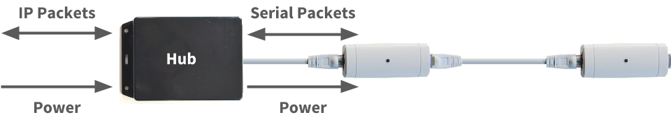
The hub converts their serial data packets into IP data packets. Some hubs may instead convert the serial data packets into some other format that a computer can, in turn, convert to IP packets. The hub also provides power to the reelceivers. We include a hub with our starter kits for out-of-the-box connectivity, but with basic tools and a little bit of effort, you can enjoy building your own hub. In this tutorial, we'll show you how!
Build a USB hub Build an IP hub
Build a USB hub
Here you'll learn how to build a USB hub which allows you to connect a reel directly to your computer, server, Raspberry Pi or anything with USB host capability. This is arguably the quickest, easiest and most cost-effective way to connect a short reel to a computing device. The only limitation is the 5VDC power supplied by the USB port: don't expect to connect dozens of reelceivers over hundreds of metres! But with a good USB port, you might successfully connect a few reelceivers over tens of metres.
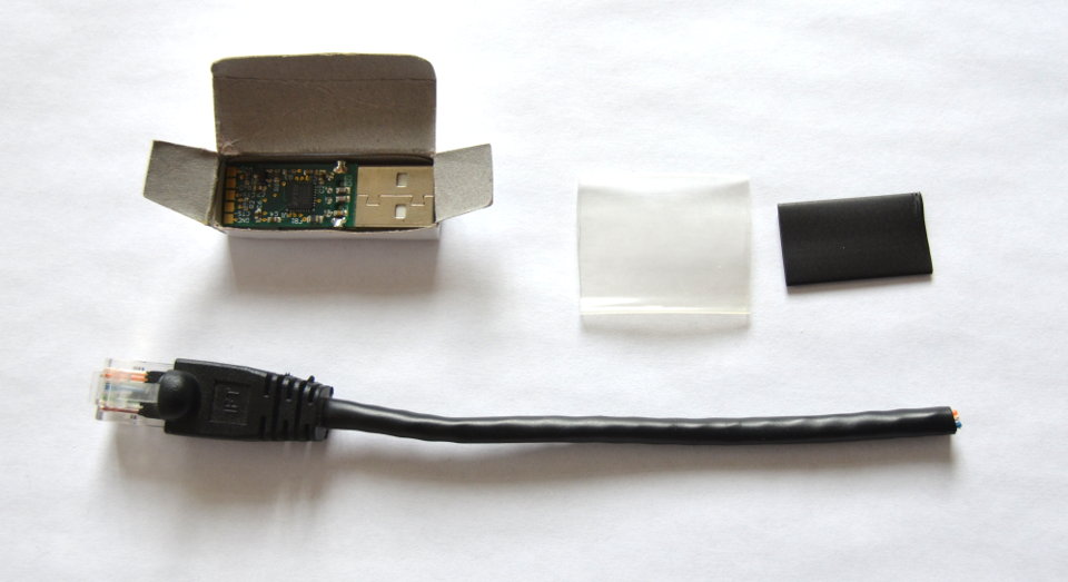
Here are the parts you'll need:
- a Cat5 cable with one RJ-45 connector (i.e. an "Ethernet" cable cut in half)
- an FTDI USB-RS422-PCB board (buy on DigiKey)
- (recommended) a 2-3cm diameter clear shrink tube cut to 3cm length
- (recommended) a 1-1.5cm diameter opaque shrink tube cut to 2.5cm length
You'll also need the following tools:
- a soldering iron
- some solder
- wire cutters and strippers (or simply a knife)
- a heat gun (or hair dryer, or lighter...)
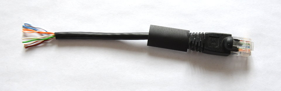
First, slip the opaque shrink tube onto the Cat5 cable. Seriously, do this first because otherwise you'll forget and then regret your mistake after you've started soldering... We're speaking from experience here! Then trim off about 2cm of the sheathing.
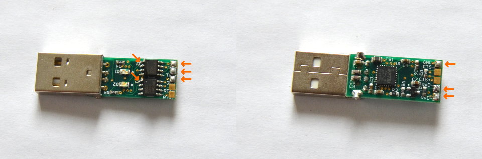
Add a touch of solder to the six indicated pads on the board. Also add a touch of solder to Pin 1 of each of the 8-pin ICs, as also indicated by the little orange arrows.
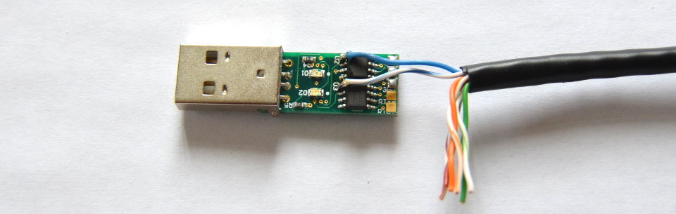
Strip 1-2mm off the blue pair of wires and solder one to each Pin 1 of those 8-pin ICs. The blue pair carry the positive voltage of the reel which in this case will be around 5VDC. Take care not to short them with any other pins!
Trim the green pair of wires and one of the brown wires so that they meet the pads shown above without bending. Then strip 1-2mm off each. Solder them to their respective pads, from top to bottom in the above image the order is:
- solid green
- green/white
- brown or brown/white (doesn't matter)
The green pair carry the serial data from the hub to the reel. Note that this is the most meticulous part of the whole operation. It helps if you can secure the board in a vise. Don't worry, after this, it's smooth sailing.
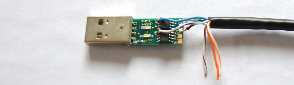
Flip the board and trim the orange pair of wires and the other brown wire so that they meet the pads shown above without bending. Then strip 1-2mm off each. Solder them to their respective pads, from top to bottom in the above image the order is:
- brown or brown/white (doesn't matter)
- solid orange
- orange/white
The orange pair carry the serial data from the reel to the hub. The brown pair carry ground, hence their order doesn't matter.
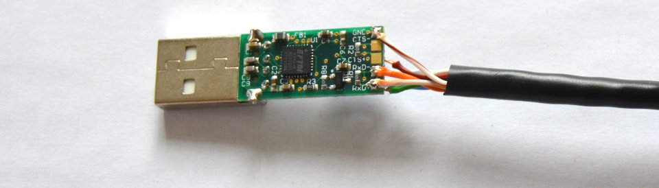
Now you (should) have a functional USB hub! This is a good time to test it out with the Barnowl Baby Steps tutorial. If the hub works we can move on to the fun part of shrink tubing it which protects against shorts and acts as a strain relief.
Place the clear shrink tubing over the assembly so that about 2mm overlaps with the USB connecter. Then blast it with the heat gun so that it makes a nice snug fit. We selected clear shrink wrap so that the LEDs remain visible.
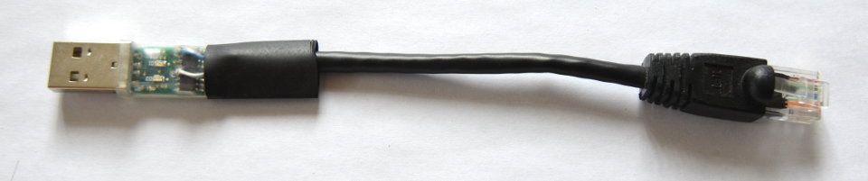
Slide the opaque shrink tubing over the assembly so that it overlaps both the board and the sheathed part of the Cat5 cable. Then blast it too with the heat gun so that it makes a nice snug fit.
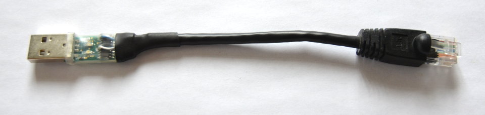
Congratulations, you've got yourself a USB hub!
Build an IP-connected hub
Here you'll learn how to build an IP-connected hub which allows you to connect a reel to an IP network via Ethernet or WiFi. Specifically, you'll learn how to create the cable harness to interface a reel with a family of off-the-shelf industrial serial-IP converters. The hub and reelceivers can be powered with up to 45VDC allowing for maximum reel lengths.
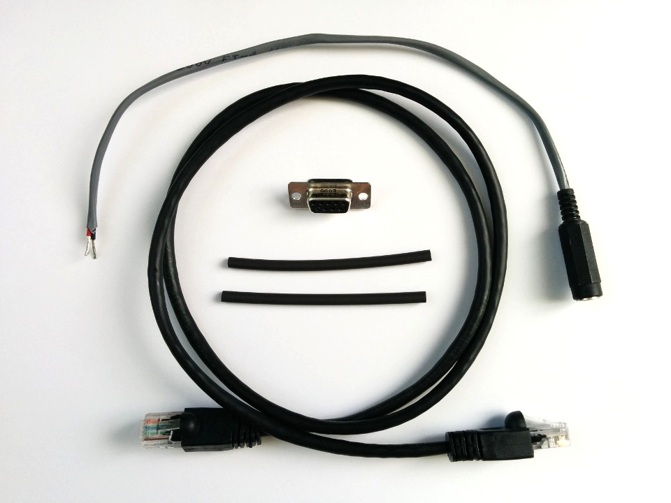
Here are the parts you'll need:
- a Cat5 cable with one RJ-45 connector (i.e. an "Ethernet" cable cut in half)
- a DB9 connector (buy on DigiKey)
- a DC power connector (buy on DigiKey)
- a two-lead DC power cable (shown pre-assembled with the above)
- opaque shrink tube
- (not shown) an Atop SE590x or SW550x serial-IP converter (buy via Neteon)
You'll also need the following tools:
- a soldering iron
- some solder
- wire cutters and strippers (or simply a knife)
- a heat gun (or hair dryer, or lighter...)
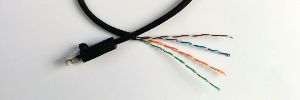
First, take the Cat5 cable that's been cut in half and strip off at least 8cm of the sheathing. This cable will connect to the first reelceiver either directly or via a patch panel, so plan ahead by choosing an appropriate cable length.
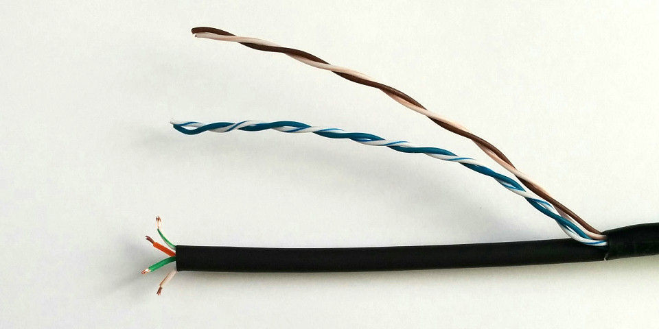
Cut a piece of opaque shrink tube long enough to cover all but a few millimeters of the exposed twisted pairs. Slide it over the green and orange pairs (these carry the downlink and uplink communications, respectively). Strip 1-2mm off each of the communications wires.
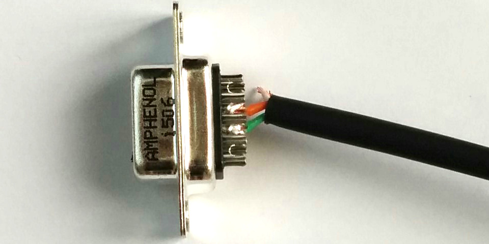
Solder the negative communication wires to the DB9 connector as follows:
- solid green ➞ pin 8
- solid orange ➞ pin 7
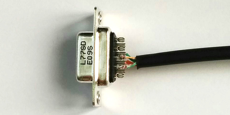
Flip the DB9 connector and solder the positive communication wires as follows:
- green-white ➞ pin 2
- orange-white ➞ pin 3
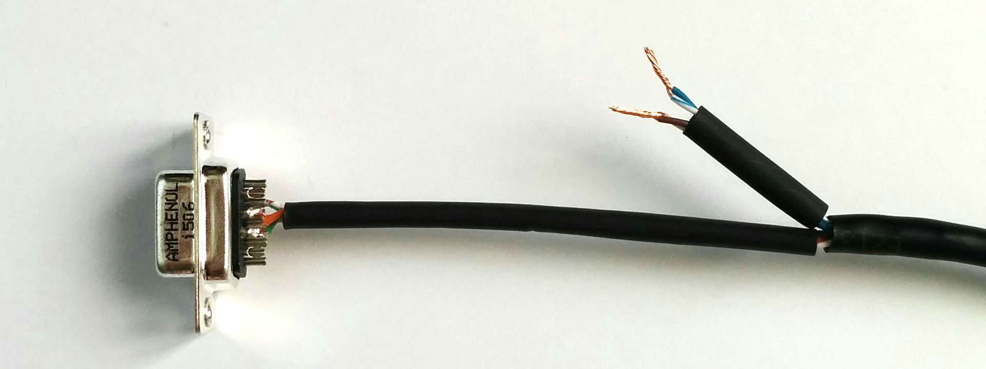
Cut the length of the blue and brown pairs down by no more than half. Strip 6-7mm off each of the wires and then twist each pair together. Cut a piece of opaque shrink tube to cover all but 1cm of the exposed twisted pairs. Slide it over the blue and brown pairs (these carry the positive voltage and ground, respectively).
Now blast all the shrink tubing with the heat gun so that it makes a nice snug fit.
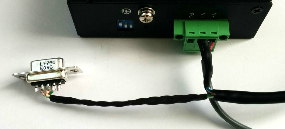
It's time to connect the cable harness to the hub. Here we'll assume you've already prepared the power connector and leads of the desired length. First we'll connect the power wires as follows:
- blue pair and positive lead ➞ V+
- brown pair and negative lead ➞ V-
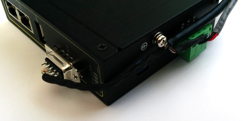
All that's left is to plug the DB9 connector into the COM receptacle and we're done! Test the setup by plugging the DC connector into a DC power supply between 9VDC and 45VDC and observe the hub powering on.
Configuration of the hub itself is outside the scope of this tutorial, but is covered in our Install A Starter Kit tutorial.
What's next?
Check out the other tutorials on diyActive to make good use of your new hub. You can also refer to the barnowl documentation to learn more about how to configure your hub for your operating system. Also, if you build your own unique hub and would like to share your project, please get in touch!